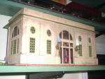


The newly formed Standard Gauge Module Association (SGMA) has accepted an invitation from the Train Collector’s Association Eastern Division (TCA Eastern) and will present an operating standard gauge modular layout at the TCA Eastern Division York toy train meet in October 2006. The layout is slated for the Black Hall at the York Fairgrounds and will feature several standard gauge operating loops, vintage and modern locos and rolling stock, and a variety of accessories.
SGMA organizer Kirk Lindvig developed prototype modules earlier this year based upon Sievers bench work. Prototype modules were displayed for SGMA members at York in April. SGMA participants thoroughly discussed the details of the proposed modules and voted on a set of standards that will insure a common modular interface.
Scot Kienzlen, SGMA liaison with TCA Eastern Division meet officials, is coordinating preparations for the SGMA presence at York. Members are busy building modules and designing displays.
For more information, or to join the Standard Gauge Module Association, see the SGMA Yahoogroups homepage at http://groups.yahoo.com/group/sgma/
by Jim Kelly
Members of the newly formed Standard Gauge Module Association (SGMA) met at the York Fairgrounds on Thursday, April 20th to view prototype modules and discuss specifications and plans for the future.

Kirk Lindvig - the driving force behind the new Standard Gauge Module Asociation. All modules in these photographs were built by Kirk.
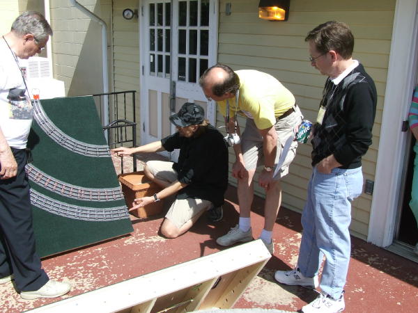
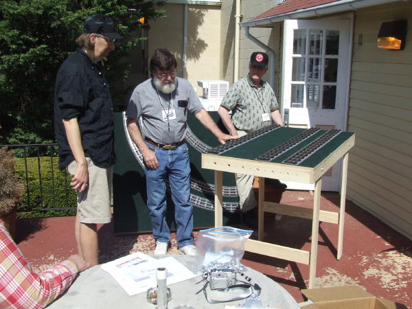
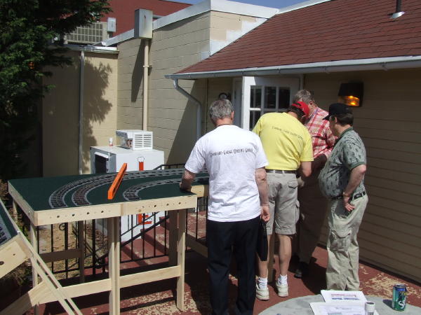
Lloyd, Bert, Kirk, and John examine a corner module.
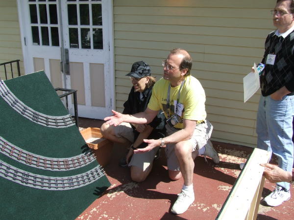
Bert (L) and Kirk (R) with a corner module.
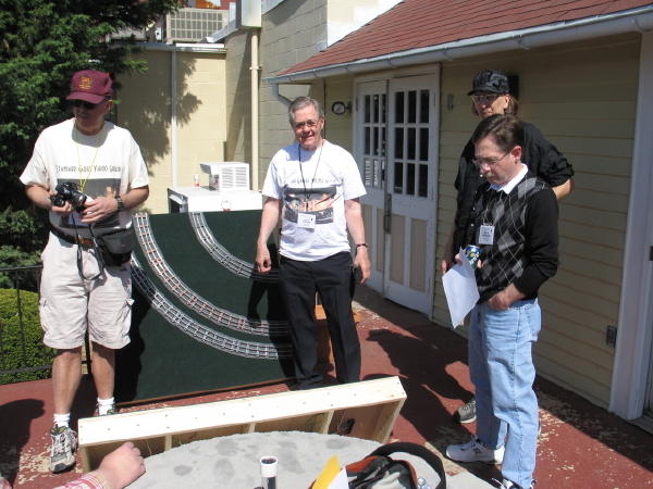
Jim, Lloyd, Bert, and John. (Photo: Kirk)
Kent assembles the legs to a 4 foot module.
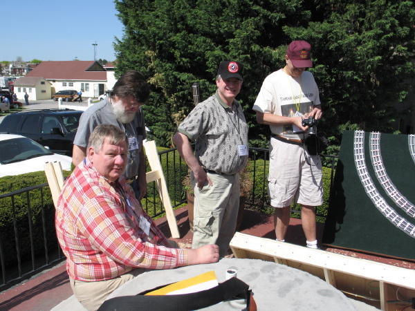
Kent, Don. Robert, and Jim with the corner module. (Photo: Kirk)
Bert, Don, and Robert with a 4 foot module.
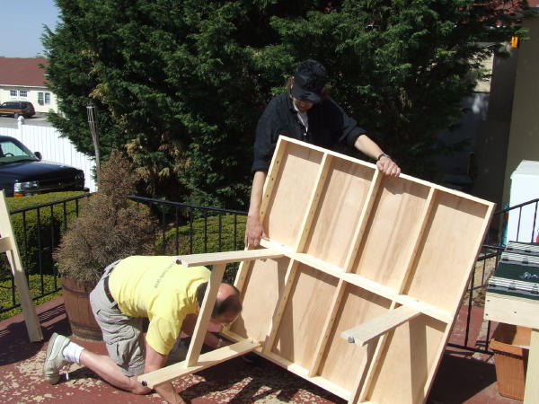
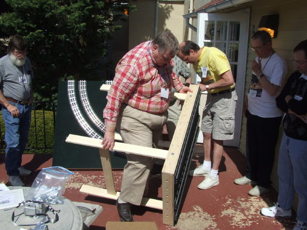
Bert and Kirk fasten the legs to a corner module.
A few more modules and we'll be ready to run some standard gauge trains!
Final version of the requirements for Standard Gauge Modules as voted on by SGMA members in June 2006, revised in January 2007, and modified effective 8-20-2011:
Interface requirements for Standard Gauge Modules
1. All modules will be 48" inches in length, or combined lengths equaling a multiple of 48" (for example two 72" long modules). Minimum module width (front to back) is 30", but may be in two pieces. Wider modules are encouraged to allow for additional features.
2. All modules will have 1/4 inch holes on four inch centers (from the front edge) centered 3 1/4 inches below the tops of the rails, on the connecting surfaces. (The Sievers 48" long Benchwork meets all requirements.) The preferred method of connecting modules together is with 1/4" bolts with fender washers and wing-nuts, but c-clamps are also acceptable.
3. All modules, or sets of modules, will have tracks centered 5-7/8", 13" and 27-3/4 inches from the front edge measured at, and tangent to, the connecting surfaces. Track ends are flush with the end of the table.
4. All modules will have legs with one inch of length adjustment. The tops of the rails will be adjustable from 42-43 inches above the floor.
5. All track will be new tubular Standard Gauge track with "extra ties"(four ties per foot). Corner modules will have the standard tubular track STD42 (actual diameter 40-1/2"), STD72 (actual diameter 70") and STD87 (actual diameter 84-1/4") curves. Actual curve measurements to the center rail.
6. All modules will have nine color coded 12 gauge stranded copper bus wires, terminated at each end of the module into a Molex 1292 series 0.093 standard 9 pin or 9 socket receptacle. The pin receptacle (Molex pin housing part number 03-09-2092 and Molex pins part number 02-09-2103) will be attached at the right end of the module as viewed from the STD42 track side of the module, and the socket receptacle (Molex socket housing part number 03-09-1094 and Molex sockets part number 02-09-1104) will be attached at the left end of the module. Both should be mounted 18" from the front of the module, and capable of extending 6 inches beyond the interfacing edges of the modules.
The color code of the wires (insulation or identifying tape color) is as follows: STD87 Hot-Black, STD87 Ground-Orange, STD87 Accessory-Blue, STD72 Hot-Red, STD72 Ground-Yellow, STD72 Accessory-Brown,STD42 Hot-White, STD42 Ground-Purple, STD42 Accessory-Green. All wire connections will be made using wire nuts, crimp connectors, solder or terminal strips (no "vampire", pinch or other connectors that may break or damage the wire strands). All connections should be made to positively prevent accidental connections between the bus wires (with insulation or other physical barriers).
Electrical separation of the three mine line tracks, including their grounds and associated accessory power supplies must be maintained at all times. Each track power supply will share a common ground only with its own associated accessory power supply. Insulated track pins should be used on all three rails whenever tracks are joined using track switches or crossings, and no track should be connected to more than one power supply or ground bus at the same time. Electrical switches should be used to control the source of power and grounding to connecting tracks, crossings and sidings. Crossing will require special care to avoid inadvertent connections between power supplies or grounds. (Note: The original MTH TIU, Rev G (no sticker on the back), had common grounds and may not be used on a SGMA display.)
Three dual or paired in phase power supplies will be used to deliver up to 10 amps of variable AC power to each of two separate outputs which share a common ground. Power supplies must have fast-acting circuit breakers. One of the 10 amp outputs of these dual or paired in phase power supplies will be connected to each main line track (not to exceed 25 volts) and the other to its associated accessory power bus (at 14 volts). The accessory power bus should be used only for supplying power to track switches (which should never be powered by track power) and to accessories which are activated by an insulated rail. Wherever possible, DCS compatible relays should be used to activate those accessories controlled by an insulated rail.
7: Carpeted modules will be completely covered with Emerald Green (Baylink Varsity brand #3788) carpet, with 4" wide strips of Smoke Grey (Baylink Varsity brand #3830) carpet representing ballast. The "ridges" of the carpet are oriented front to back to conceal the table joints. (Carpet is NOT required on modules with scenery.)
8: The outside (STD87) loop will not have any track-work which will cause operational problems with ANY Standard Gauge trains in good repair (i.e. in gauge wheels, etc.). This may require modifications to commercial switches. MTH STD42 and SDT72 switches are the standard switches be used on the STD42 and STD72 loops. Other switches, in good repair and without functional problems, are also acceptable on the STD42 and STD72 loops. This may limit older large gear locomotives, large locomotives, trolleys and possibly other equipment to the STD87 loop.
9; Changes in track elevation will not exceed 3/16" per foot on the STD42, STD72 and STD87 loops.
10: Operational tracks will be no more than 36" from at least one edge of the table.
11: The primary loops may be separated if the tracks are eventually returned to the standard interface. (For example, a corner module with two tracks continuing straight and one curving.)
12: Modules will be fitted with a laminated fascia board, fabricated by gluing a 1-5/8" high piece of 1/4" thick stock wood trim to the bottom of the side of a 1x4 board (actual size 3/4"x3-1/2"). The space above the 1/4" trim piece allows a piece of 1/4" clear plastic to be clamped between the fascia board and the module frame with the bolts that secure the legs and the fascia to the modules. Holes are drilled through the laminated combination exactly 1" from the bottom, 8" from each end, and in two additional locations at multiples of 8" from the ends. When the fascia board is bolted to the module using these holes it will be offset up 3/4", allowing it to cover the edge of the module plywood top and carpeting. The entire fascia board should be painted with black paint to seal it and to cover any possible exposed wood. A pleated skirt 40 inches in length will be attached with Velcro to the front fascia board.
13: A "Modulator" will be designated for each display activity. He will coordinate how many modules will be brought, how they will be joined, and who will be responsible for assembly, displaying and disassembling the display.
© 2006 Tinplate Times - All rights reserved.